The term “motion control” spans a wide range of applications that involve controlling the movement of a linear or rotary axis to achieve a goal such as moving to a specified position or precisely following a defined path. And although there are numerous variations, at their core, many of these applications can be grouped into one of a few general categories: pick-and-place, positioning (linear or rotary), path following (such as dispensing), winding, and flying shear.
Flying shear applications typically involve cutting a moving web of material into predetermined lengths “on-the-fly,” without stopping the movement of the material web. Although flying shear maximizes productivity, since the material doesn’t slow down or stop during the cutting process, it can be a particularly challenging application to achieve because the cutting tool (referred to as the “shear”) must be precisely synchronized with the material web — otherwise, the cut may take place at the wrong position or be incomplete, leading to material scrap and downtime.
Flying shear can also be used for crimping, stamping, embossing, and even on-the-fly inspection.

Considered a type of reference/follower system, in which the motion of the follower axis is determined by the motion of the reference axis, flying shear applications are typically defined in four phases:
Acceleration: The shear accelerates to match speed of material web.
Synchronization: When the shear speed exactly matches the speed of the material web, the shear switches to constant velocity and maintains that speed while the cutting operating is performed. The synchronization phase can be further broken down into settling time, cutting time, and rise (or retract) time, based on the movements of the tool.
Deceleration: Once the cut is complete, the shear rapidly decelerates in order to minimize the amount of material movement that takes place during this phase.
Repositioning: The shear moves back to the initial position so it can repeat the cycle for the next cut.
Synchronization of the reference and follower axes is typically done via an electronic cam linking the movement of the shear to the movement of the material web. The material web can be operated in an open-loop system, but an encoder is required on this axis to communicate its position to the controller. The shear, on the other hand, is operated in a closed-loop system, with its motion determined by position of the web feed together with the cam profile programmed into the motion controller. The cutting tool is activated when the shear and web are synchronized and the shear is in the correct position.
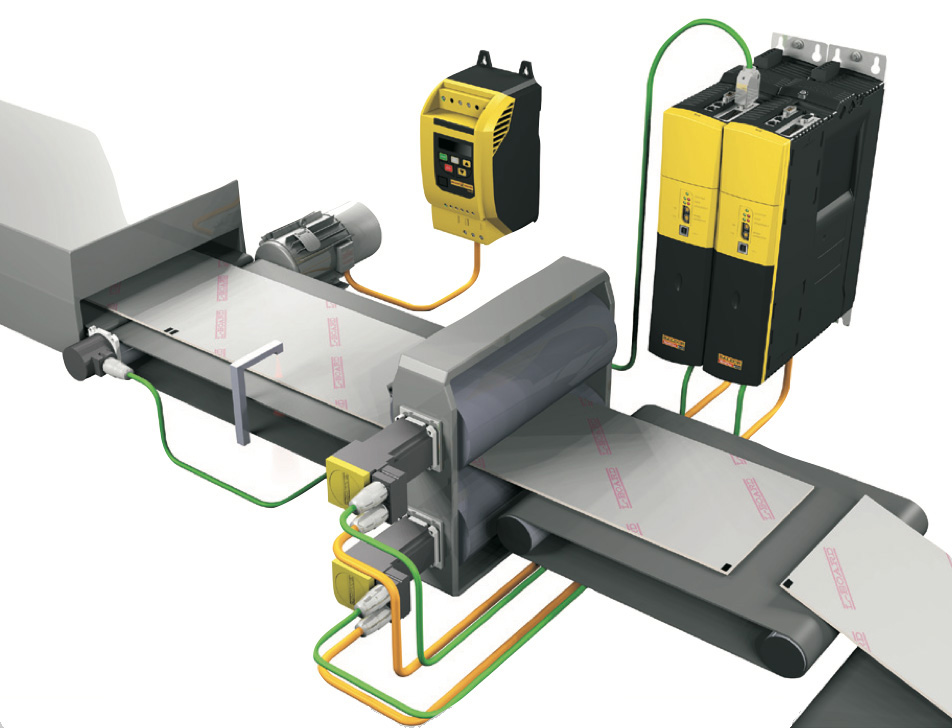
Image credit: ABB
There are two subtypes of flying shear: parallel, in which the cutting tool moves parallel to the material flow, and angled, in which the cutting tool moves at an angle to the material flow.
Parallel flying shear is used when the entire cut is done at once, as with a blade or punching tool that spans the width of the material to be cut.
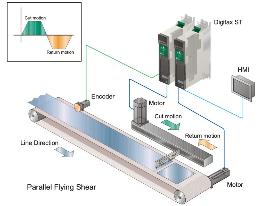
Image credit: Control Techniques
Tools such as saws or plasma cutters must move across the material in order to make a cut. In these cases, if the tool were to simply cut straight across the material as the web moves, the resulting cut would be at an angle. But the goal is typically to achieve a cut straight across the material (at 90° to the direction of the web movement), which means the cutting tool must move at an angle to the material flow. The angle and speed of the tool’s motion, together with the speed of the material web, determine the angle at which the cut will be made. For a given web speed, the greater the angle of the tool’s motion, the faster the tool will have to traverse across the web in order to achieve a 90° cut, straight across the material web.
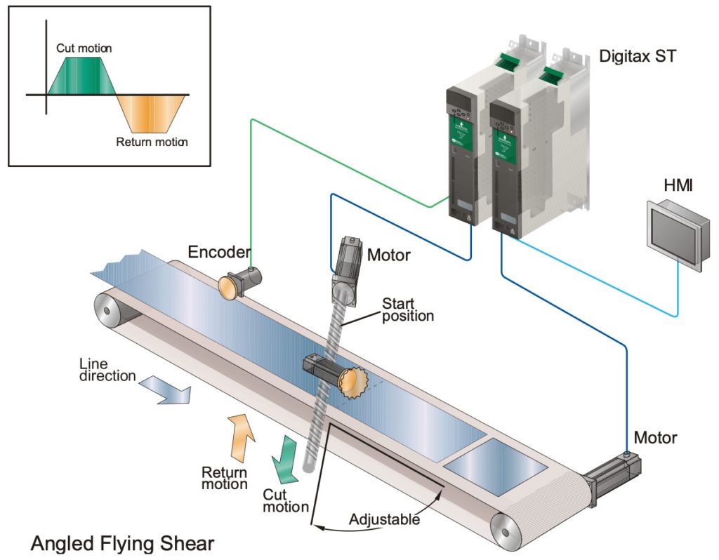
Image credit: Control Techniques






Leave a Reply
You must be logged in to post a comment.