Industrial six-axis robotics often integrate frameless motors at their axes. Over the last decade, permanent-magnet brushless servomotors have come to dominate. Increasingly common in six-axis robotic assemblies are frameless and direct-drive variations.
A high motor pole count (with strain-wave gearing) yields high torque output and low cogging. Often completing such assemblies are an absolute encoder for closed-loop position control and a safety (normally closed) holding brake for safe power-off load holding.
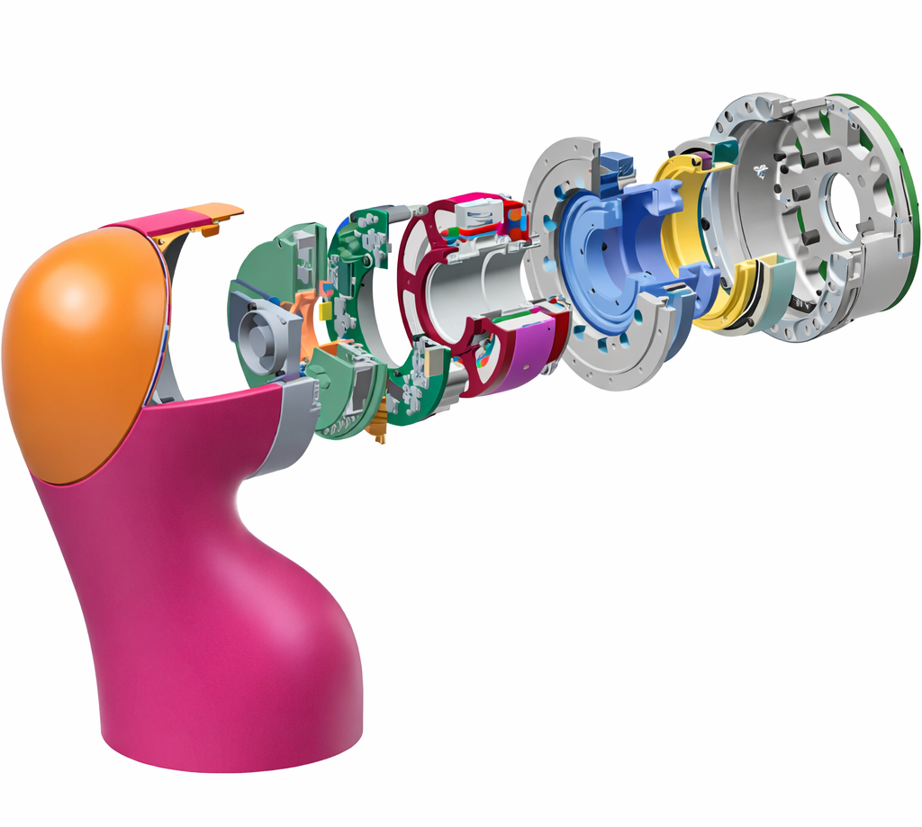
Other torque motors are used sans any gearing for direct-drive operation in inspection robots and some surgical or metrology arms needing true zero-backlash operation.
Using the “shoulder-elbow-wrist” analogy to reference degrees of freedom, adaptations of field-oriented control along with customized rotor geometry and windings can tailor robot shoulder and elbow-joint behavior to arm and payload masses. Current to windings acting upon a large magnetic airgap impart stiffness and torque density.
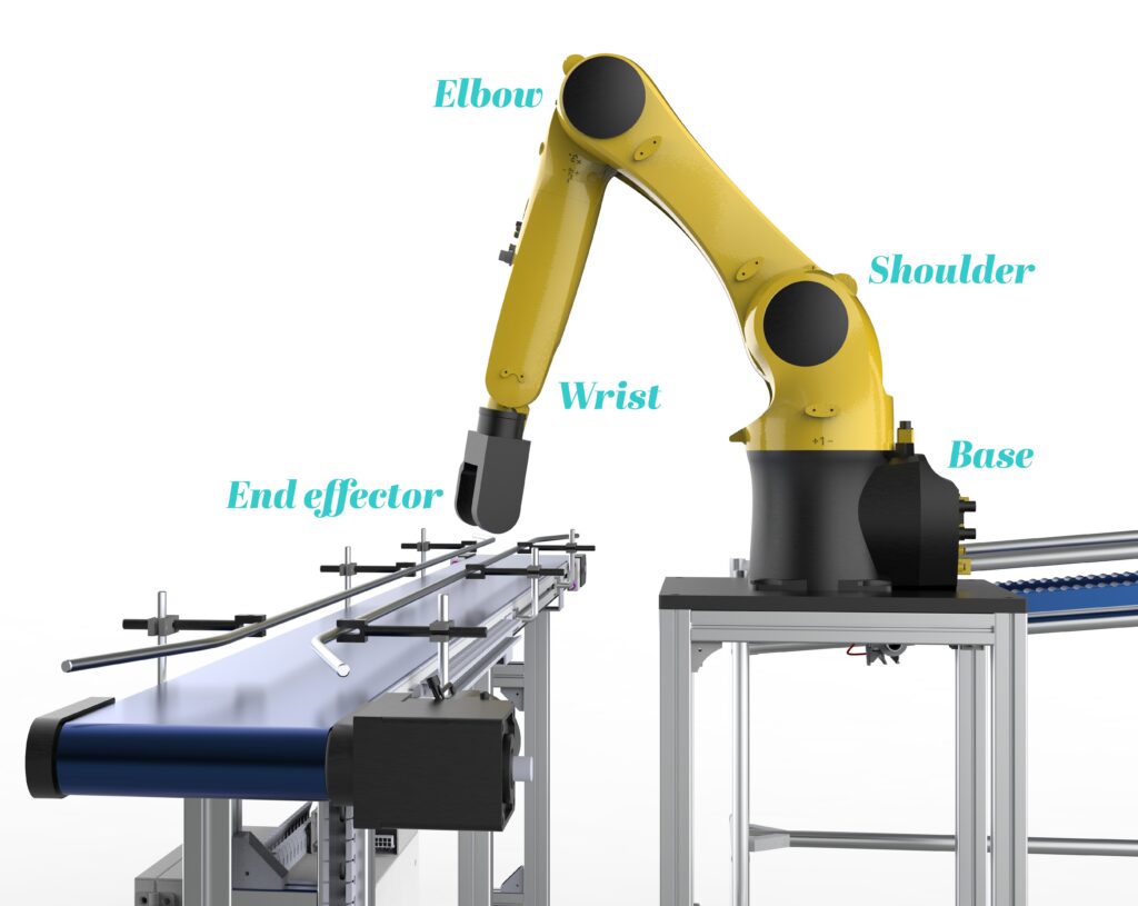
In contrast, the motors for wrist roll, pitch, and yaw joints must be lightweight with low inertia sans vibration. Even here though, permanent-magnet ac servomotors still dominate … though they’re more likely to have frameless construction or even axial-flux a.k.a. pancake-type construction. Motors in these joints are also smaller because total loads are obviously smaller at the robot extremity. The high torque density of PM motors is key.
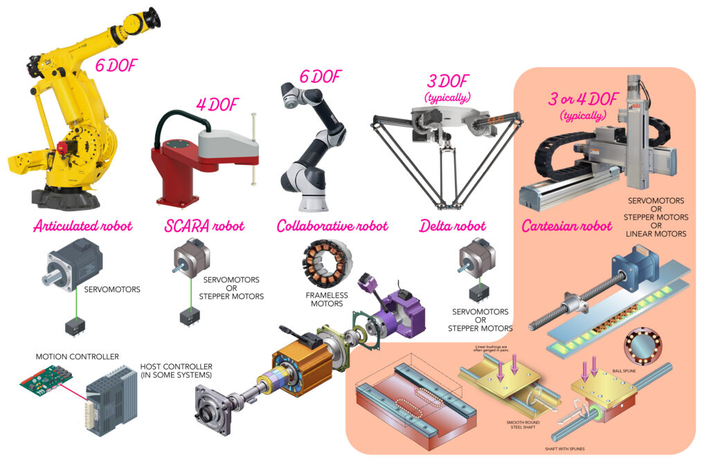
Like articulating six-axis arms, many SCARAs (as for horizontal assembly and pick-and-place tasks) also integrate high-torque ac servomotors on their planar rotary axes for quick accelerations and fast settling. Their vertical Z axes can feature servomotor-driven screw drives (as mentioned earlier) or even linear motors.
Same motors … increasingly similar overall
Recent years have brought convergence of articulated industrial robots and collaborative robots as frameless motors have become more common in the joints of both. Both robot types are also making increased use of machine learning and AI — especially industry-specific AI and “physical AI” built for a single function such as welding, sanding, inspection, or assembly.
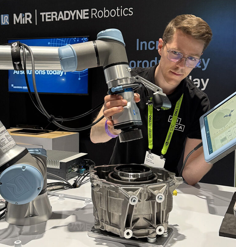
The convergence of articulated industrial robots and cobots is also seeing more overlap in payload ratings.
Related: Embedded motion and frameless motors in collaborative robots
Related: Four physical AI predictions for 2026
Payload mass and moment inertia of course includes that of the moved robotic linkages, end effector components, and any actual workpieces being handled. With some robots, if a temporary derating of speed, acceleration, and precision is acceptable, it might be possible to occasionally exceed rated payload — so long as operations remain lower than any maximum payload defined.
The gearing in today’s non-Cartesian robotics
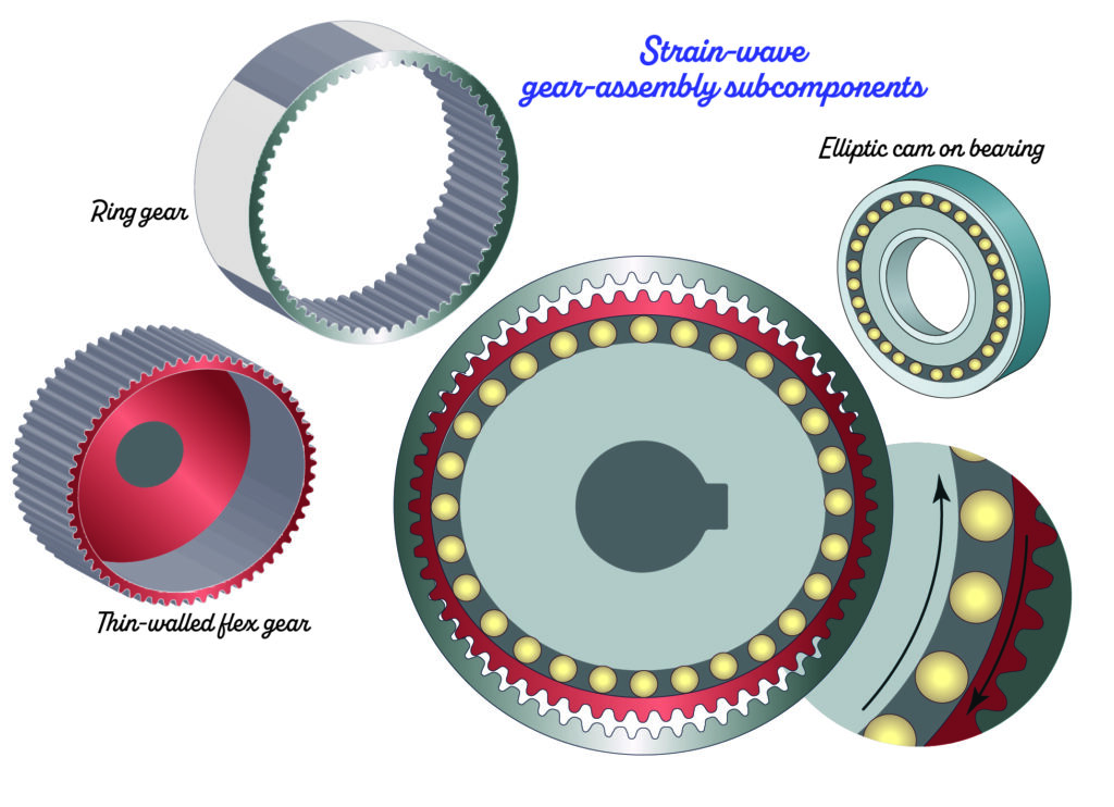
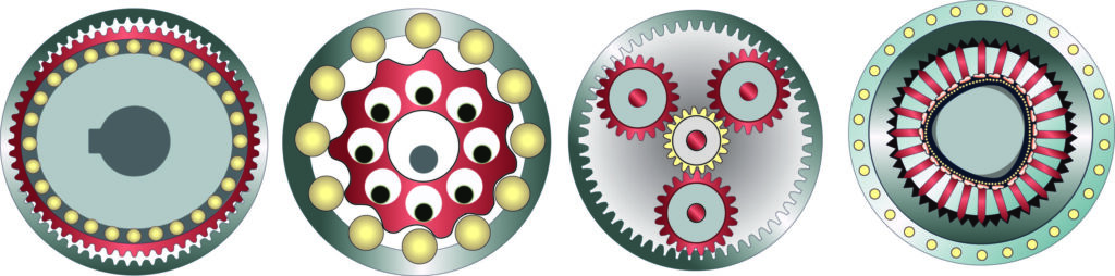
Robotic joints often have cycloidal gearing as well as gearsets relying on wave-inducing subcomponents having an elliptical or Reuleaux (pronounced roo-low) or other polygonal shape. Planetary and strain-wave gearing dominate, though proprietary cycloidal solutions see use in specialty robotics.
Related: How do cycloidal gears work and where are they used?
Case in point: New FluxWorks magnetic-gearing technologies use modulated magnetic fields to exert force without contact. Stay tuned for more on this technology soon — especially as it relates to robotics applications.
Yet another established gearing option for robotics now seeing increased use has two names:
- Cycloidal gearing.
- Rotary vector or RV gearing as coined by one manufacturer.
At first glance, cycloidals resemble trochoidal gearing used in certain pumps … but the technologies shouldn’t be confused.
Quick geometry lesson here … trochoidal and cycloidal gearing includes elements that rotate and trace curves around another element. Cycloids traced by a point on a rolling element’s circumference include:
- Epicycloids (for which the element rolls along the outside of a sun gear or other reference component).
- Hypocycloids for which the element rolls within a ring or other reference component.
In contrast, trochoids are traced not by a point on the rolling element’s circumference but rather some point within or without.
Technically, planetary sets are a kind of epicyclic gearing.
For planetary or strain-wave gearing, representative ratios are 50:1 to 200:1 … though can be lower at six-axis robots’ wrist joints. Among other things, such gearing boosts acceleration torque for power density — key for six-axis robotics as well as SCARAs for which the assembly is basically a cantilevered mass.
Suspension changes seventh-axis gear choice
Below we have gearing examples from GAM Enterprises on each axis’ motor in two robot arms. Gearing types differ for different arm arrangements. For example, the most suitable gearing in the pinion (and carriage) driving gearmotor of an articulated robot seventh-axis system in part depends on the robot’s orientation in space. The seventh axis of floor-mount systems often have a right-angle hypoid gearbox. Most commonly “gantry” refers to cartesian arrangements … though suspended six-axis robots also qualify. These suspended gantries often have a helical inline gearbox. Just to be clear, both help power rack-and-pinion sets having helical tooth geometries.
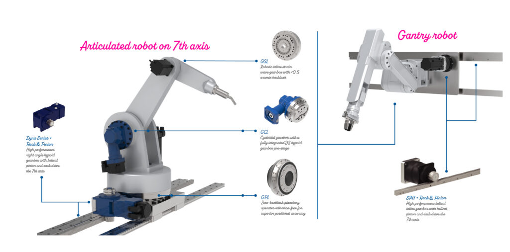
The right-angle gearbox for the floor-mounted track does a few things: It avoids the robot’s envelope, a long drive in the travel direction, and awkward mounting. Instead, a right-angle arrangement keeps the motor low and tucked alongside the carriage for a stiff and tidy assembly. Hypoid gearing excels on rack-pinion drives because of their high torque and ruggedness on reversing axes like this subject to shock loads from normal operation and emergency stops.
Technologies in miniature robotics
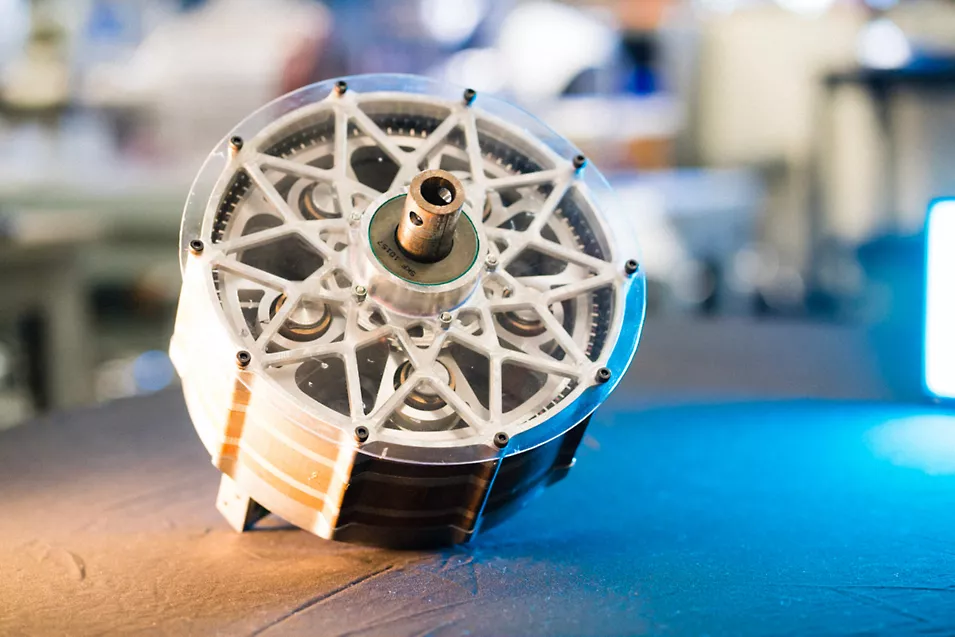
To illustrate how other components come together, let’s consider Chieftek Precision (cpc) S0 miniature robotic arms. These move payloads to 1 kg with infinite maneuverability from multiple joints. 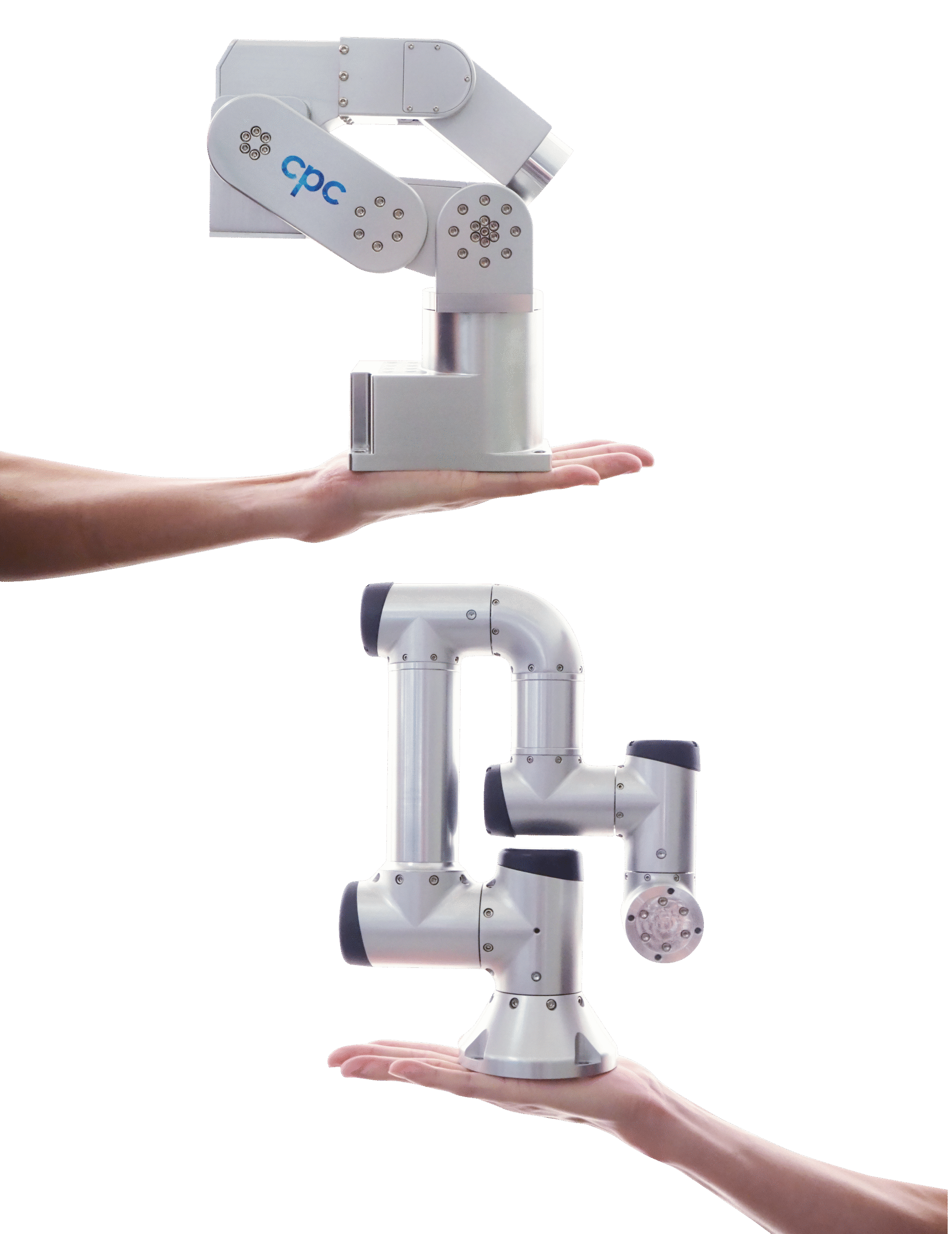
A DB0 version (top) offers slightly less maneuverability for higher stiffness and ±5.0-µm repeatability. Both robotic arms integrate more than 200 separate parts mostly designed and manufactured by Chieftek:
- Custom large-bore frameless motors (accepting 48-V input) impart motion at each joint.
- Strain-wave gearing with high ratios maximize torque.
- Dual-feedback systems at each axis with an absolute optical encoder and an absolute magnetic encoder sandwiching the gearing to ensure repeatability.
Motor drives with cool-running driver electronics and power stages complete the miniature designs.
Related: Why are planetary gearboxes preferred for servo applications?
Related: Inertia matching: Why perfect isn’t always best
Now let’s turn out attention to the one type of robot we haven’t detailed yet — X-Y-Z cartesian robots. The cuboid reach of cartesian gantries or really any variation are easy to envision. These systems are most suitable where the end effector can execute its tasks in a given orientation within a plane. In fact, cartesians are a preferred solution for especially large workcells … and for such situations, often more cost effective than a fleet of even very modest SCARA robots. For smaller workcells, cartesian robots can prove a more expensive solution.
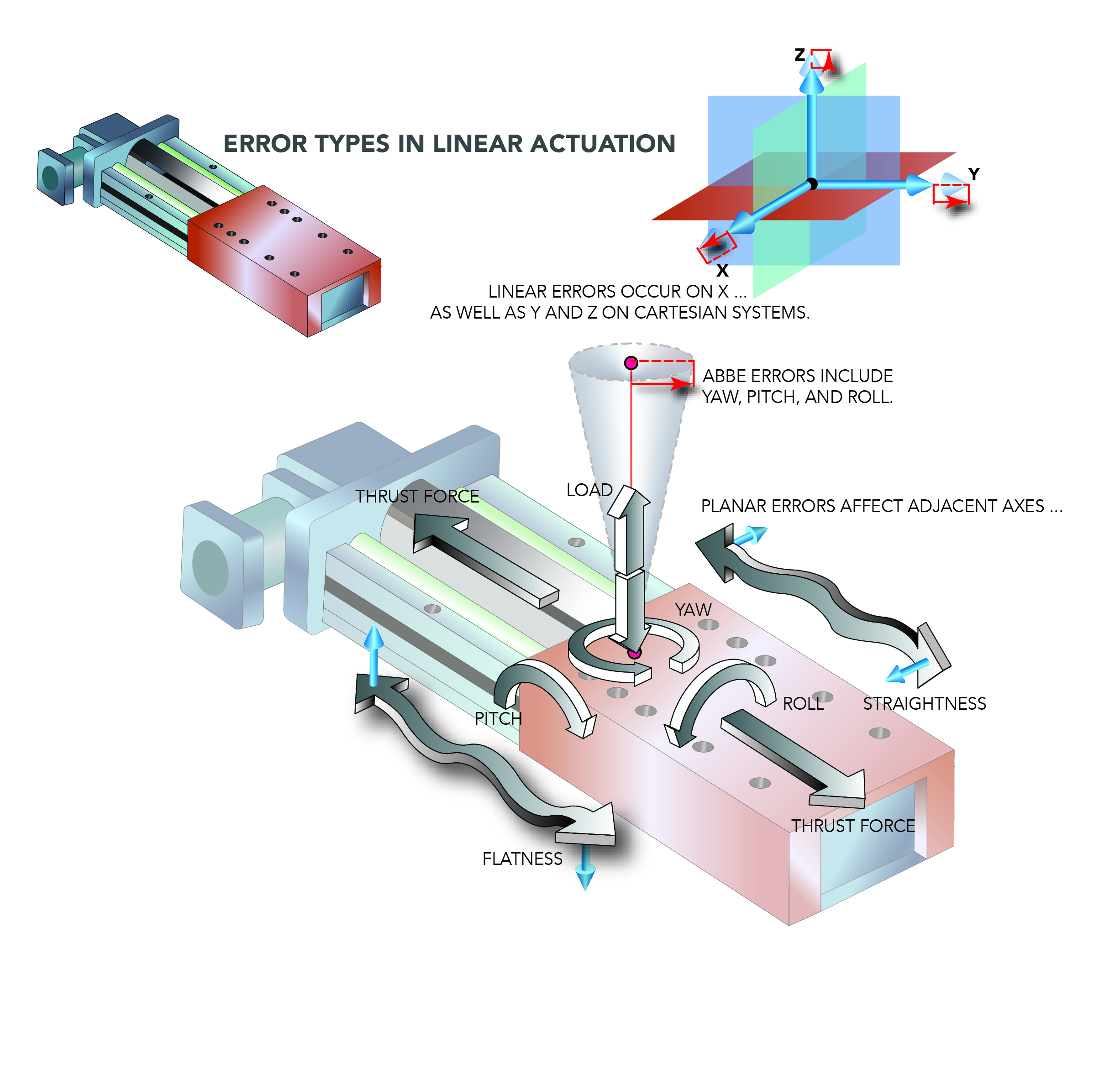
Cartesian-robot axes are never perfectly perpendicular. So, end-effector repeatability about each of axis depends on that of each drive as well as the amount of motion coupling between the axes … with error increasing as each axis gets farther from its home position.
Another consideration: Compared to that of articulated robot types, the integration and routing of end-effector supply lines (in the forms of cables, hose, carriers, and service loops) is also more involved.
That said, a cartesian robot customized to a large-scale production can satisfy exact requirements like no other option. These kinds of situations justify relatively high upfront costs with long-term efficiencies, output volumes, and scaling of operations.
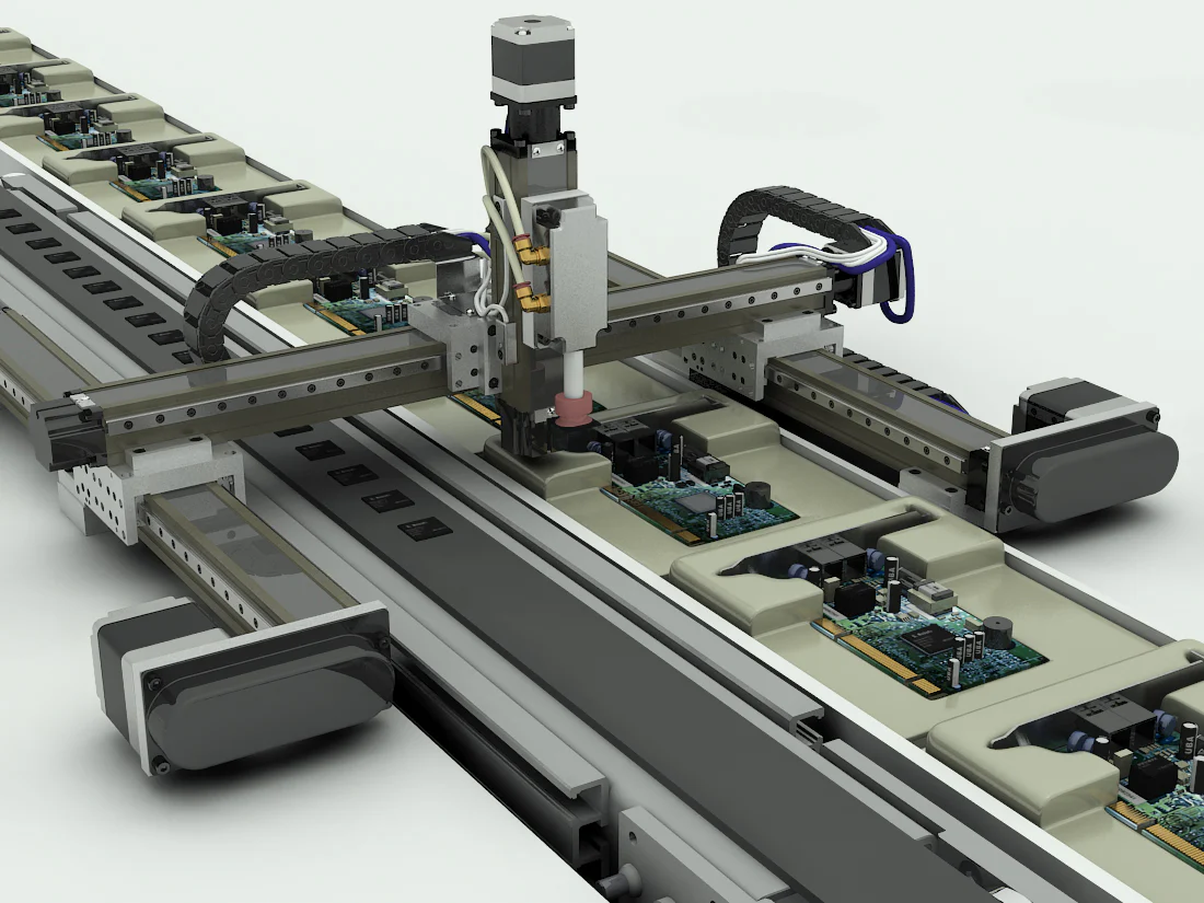
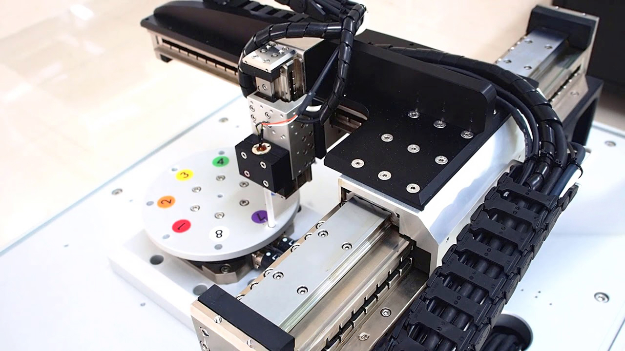
Below we see two very different cartesian robots. In both though, modular hardware along with certain controllers and communications reduce design complexity.
PBC Linear guides and belt or leadscrew-driven servo or stepper-motorized axes combine to form custom robotics for part handling, vision-based alignment, and other synchronized motion in packaging, assembly, and inspection. The example here is an arrangement with stepper motors and screws to automate circuit-board assembly.
Likewise, Chieftek Precision linear guides and linear motors complete vision stages, press modules, and laboratory workcells needing fine positioning or part transport with extremely high rigidity and repeatability.
Leave a Reply
You must be logged in to post a comment.