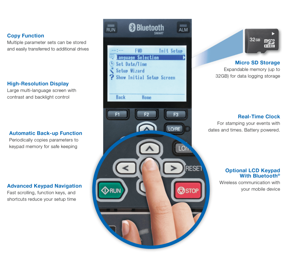
Variable frequency drives have an incredible amount of functionality. Due to advancements in technology over the years, HMIs in the form of VFD keypads have become more user friendly with easier navigation, higher resolution displays, and more detailed setup wizards.
By Jonathan Kopczyk | Technical support engineer • Yaskawa America Inc.
Looking back at the past decade, it’s clear that variable frequency drives (VFDs) positively impacted the motor control industry. These devices can precisely alter the output frequency and voltage to a motor for accurate speed control and response, all while maximizing efficiency. Variable torque loads such as centrifugal pumps, fans, and blowers are run by VFDs around the clock, keeping spaces temperate and water flowing for everyday use.
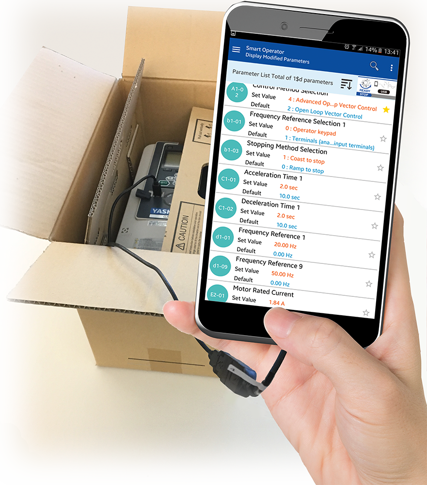
One industry trend is the rise of VFDs that accept programming, monitoring, and operation via commands received on a smartphone or laptop. This makes setup and programming easier — and it puts product literature and video tutorials at end users’ fingertips. Some VFDs can even be programmed without main power connected.
It is important with these types of applications that the VFD is setup correctly and a proper startup is performed at some point. This generally includes terminating any control wiring and altering parameter settings if necessary.
Though it may seem intimidating, programming a VFD isn’t as hard as it sounds. There are numerous ways to go about the process … and in some situations, little to no change is required.
Basic VFD parameter settings
Say you’re tasked with programming a VFD for an HVAC application and your knowledge on it is very limited. What exactly needs to be setup? Well, this answer may depend on a few factors — though in most cases, there is not much required.
- First off, because the VFD is also used as a means for protection, the motor full-load current (FLA or amperage) must be entered. Other motor nameplate specifications including maximum rated voltage and RPM (or number of poles) should at least be verified with their corresponding parameters. Typically though, the default settings are on par.
- There is also a feature commonly known as auto-tuning available on most VFDs. Though not necessarily needed with variable torque loads, auto-tuning functions provide an alternate way to tune the motor for the application.
- Lastly, the run or start-stop command and speed-frequency signal must be addressed. A dry contact for run and analog input for speed are usually what the drive requires by default.

Next in basic parameter setting are those values that may not necessarily require change — but are highly desired for most variable torque applications. The majority of these settings may even appear when completing a setup wizard or changed when an application preset is selected.
- First consider acceleration and deceleration times: These affect how quickly the motor will ramp from 0 to 100% speed or vice versa.
- The stopping method can also be adjusted. This determines the VFD’s reaction when the run command is removed. A coast-to-stop method is usually the default and sufficient with variable torque applications.
- Next are minimum and maximum speeds which can put a limit on the VFD output frequency. For example, it may be necessary to set a minimum speed for a pumping application to assure continuously moving fluid.
- Lastly, VFDs have the ability to auto-start after a power glitch or blackout. Though usually disabled by default for safety reasons, this feature can be a lifesaver in critical scenarios.

More advanced VFD parameter settings
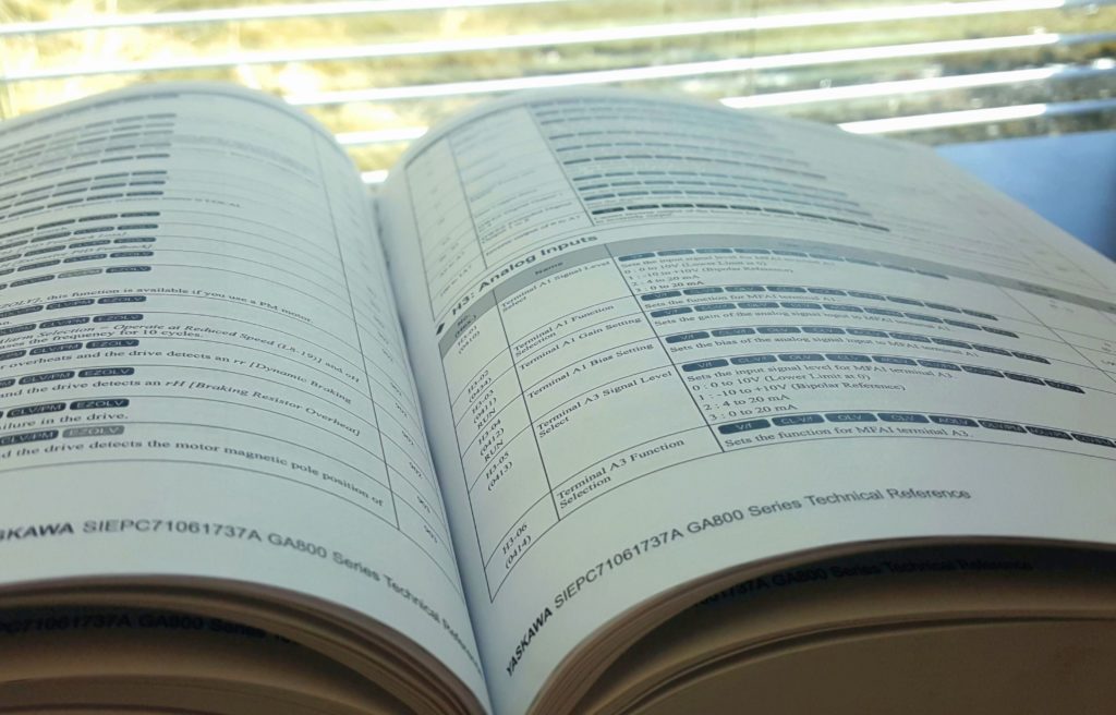
Browsing through the hundreds of parameters in a VFD manual can seem intimidating. However, there are a few advanced ones worth noting.
First and foremost are volts per frequency (V/f) settings which affect the performance of the motor. As the drive ramps up or down, the output frequency and voltage change according to a predefined pattern. Therefore, adjusting these settings can alter the speed and torque profile of that motor.
Another parameter that can change how the VFD outputs is the carrier frequency. This is basically the resolution of the VFD output waveform. There are both advantages and disadvantages of setting high and low carrier frequencies.
Yet another setting is that of output current. It’s commonly known that VFDs monitor output current for motor protection. As a benefit to the user, both over-torque and under-torque levels can be set where the drive will fault or provide an alarm if certain conditions are met. This is especially useful when monitoring for low current conditions — which occur when a belt breaks in an HVAC application, for example.
Other advanced settings include optimizing the keypad, assigning a function to the analog and digital inputs and outputs (I/Os) if necessary, and allowing the VFD to start the motor on-the-fly — commonly known as speed search.
Don’t assume special expertise is needed to make simple programming changes to a VFD.
Application-based settings on VFDs
As their popularity grows, it’s no surprise VFDs are becoming more tailored for specific applications. This not only provides a huge benefit to the consumer as needs are easily met, but the functionality is maximized as well. For example, parameter settings specifically designated for fire-alarm control or emergency override may be present in a VFD for an HVAC application. In the pumping world, where pressure control is essential, advanced proportional integral derivative (PID) parameters keep pressure at bay while protecting system components. It is also not uncommon for multiple drives to be linked together to ultimately meet one goal. This just requires a few extra steps when programming.
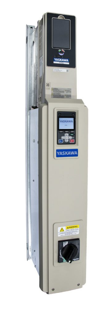
There are also bypass units which contain a VFD, contactors, and other components to run the motor across-the-line when needed. Switching from drive to bypass or the opposite can be done based on many different settings and options.
Verification of VFD variables
Once the initial setup has been completed, it is recommended to perform a test run to check several variables. The motor can first be “bumped” to check rotation: This involves a quick start-stop procedure. If rotation is incorrect, swapping two of the VFD output motor leads is the preferred method to fix this issue. A parameter setting may also be available to modify, but if the VFD is ever put back to default then the rotation will just change back to reverse.
Once this has been established, output current (amperage) should then be verified when the VFD is running. This can be done by viewing the keypad monitors or checked with a clamp-on type multi-meter.
If output current is slightly high, altering a few parameter settings may help in some situations. Otherwise, it’s best to verify the motor and load are in good working condition.
Lastly, any I/Os connected to the VFD need to be checked for operation. Because these can make or break the application, it is crucial that the corresponding parameters are set based on the needs of the user.
Yaskawa America Inc. | yaskawa.com





Leave a Reply
You must be logged in to post a comment.