Updated November 2018 by Lisa Eitel • Motion applications for gearing are as varied as the motors with which these power-transmission devices pair. Just consider how designs ranging from amusement rides to consumer-grade beard trimmers make use of spur gears. These mostly roll through meshing, so can be 98% or more efficient per reduction, though with tooth sliding. They can be noisy, too, because of initial tooth-to-tooth contact along the whole tooth width, causing audible shock loads.

In contrast, helical reducers excel in applications that need higher horsepower and efficiency, even if they’re more costly initially. Conveyor drives, textile-manufacturing machinery, rolling mills and elevators are some examples. That’s because helical gear teeth engage gradually over their tooth faces for smooth operation and higher load capacity. Here, the machine setup must include a frame to resolve thrust loads that originate from the gears.

Non-parallel and right-angle gearsets often go into designs for material handling, aerospace and defense, packaging equipment and food-processing machinery.
Input and output shafts protrude in different directions; gear teeth are worm, hypoid, bevel (straight, spiral or zerol), skew or crossed-axis helical. Common bevel gearsets go into an array of material-handling and packaging equipment. Hypoid gears (useful for high-toque applications) are like spiral-bevel gearsets, but output and input shaft axes don’t intersect, which simplifies the integration of supports. Common in aerospace, zerol gearsets have curved teeth that align with the shaft to minimize thrust loads.

Gear reducers or speed reducers work with an array of motors. These are gears or sets that alter the torque of a motor—usually as an increase proportional to rpm reduction.
Especially common in material-handling setups, shaft-mounted gear reducers come in truly shaft-mounted designs that use special couplings to address reactionary torque. Other shaft-mounted reducers actually mount to the machine housing (especially in machine setups with surrounding enclosures) so the input shaft doesn’t support the reducer.


According to the American Gear Manufacturers Association (AGMA), the term speed reducer applies to those with pitch-line velocities not exceeding 5,000 fpm or pinion speeds not exceeding 3,600 rpm.
Consider worm-gear reducers. These typically go into low- to moderate-horsepower applications (largely because they have high ratios and high output torque, but are compact and cost effective). Most worm gears are cylindrical with teeth of consistent size; some worm-based reducers have double-enveloping tooth geometry (in which pitch diameter goes from deep to short and back) to boost teeth engagement.
Metal cutting and forming machinery, construction equipment, and packaging machinery all benefit from the low backlash of this gearing type. To illustrate, printing-press rolls hold tight print registration at high speeds thanks to the ability of double-enveloping worm gearing to resist shock and withstand extreme acceleration. The low inertia of this gearing also lets presses start and stop more quickly than those with multi-stage gearing.


Gearheads, much like gear reducers, are useful where applications call for high torque at low speed. They reduce a load’s reflected mass inertia, so ease the acceleration of big loads … which in some cases, even lets machines run off smaller motors. Gearheads range from basic spur gearheads to complex planetary gearheads and harmonic gearheads, all exceling in select applications.
The latter (also called strain-wave gearing) is for special speed-reduction applications. More specifically, this gearing is indispensible in robot-arm articulation, medical equipment and offshore drilling. (Strain-wave gearing sets are called Harmonic Drives, a registered trademark term of Harmonic Drive Systems.) Strain-wave gearing helps designs with zero backlash and high-torque operation from a small package.

Much machinery integrates servogears into application-specific electromechanical arrangements, and several of these arrangements are common enough to have their own labels.
Gearmotors (most useful in machines that move heavy loads) include a gear reducer integrated with an ac or dc electric motor. Gearboxes are contained gear trains; planetary gears are a common form. Planetary gears are particularly common in servo systems. Usually, the planet gears mount on a movable arm that rotates relative to a sun gear. In most applications, an outer annulus meshes with the planet gears.


In fact, planetary gearsets offer applications several advantages over other gearsets—multiple kinematic combinations, power density, big reductions from volume compact setup and pure torsional reactions.
Planetary gearboxes also boost overall design efficiency. Losses never exceed 3% per stage, so transmit most energy for productive motion output. Planetary gearboxes distribute load efficiently as well.
In applications driven by servo systems, gearboxes also reduce settling time (which is a problem when load inertia is high compared to motor inertia).

Gear-selection tool helps robot-maker KUKA
Consider one specific application. Now, KUKA’s KR AGILUS industrial robot uses a new KL 100 linear robot-transfer unit (RTU). This track helps to boost speed and manufacturing quality, even in tight spaces. Core to the development and optimization of the drivetrain was Graessner USA’s Gearfox software.
In short, KUKA needed an efficient, extremely compact gearbox for its KUKA KL 100 RTU. So, company engineers used Gearfox to incorporate relevant operating conditions. The software even helped the engineers simulate the gearbox thermal balance. Engineers also used the software to identify and analyze the next smaller and next bigger gearbox variants possibly viable for the application. In the end, they picked a DynaGear set.
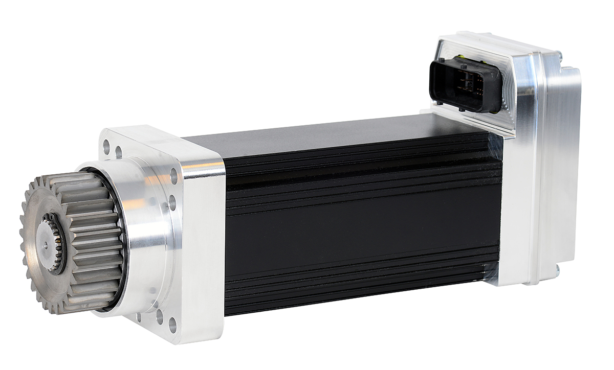
The internet-based software gave KUKA engineers assurance that the DynaGear gearbox would fulfill all design requirements (dynamics, durability and thermal stability) before physical testing.
No matter the application, MS-Graessner Gearfox software helps designers consider each design task as a challenge with multiple viable solutions. These include variations with different drive elements, including gearboxes. First, the software profiles the application needs, including definition of product requirements and variations in the application itself. Then it analyzes different gear-design permutations and culminates with iterative gearbox optimization. Factors that Gearfox uses in calculations and permutation simulations include application speeds and torques, bearing durability, gearing forces and efficiencies, moments of inertia, axial and radial forces, square, cubic, quartic and quintic motion cycles, and the profiles of an array of servomotors. The software also uses profiles of seven predefined application types and five predefined gear types in its calculations.




Leave a Reply
You must be logged in to post a comment.