For a given motion profile, when are other options for stopping insufficient — and a clutch or brake necessary? Good question. At the core of most motion axes are electric motors. Stopping loads on their axes can be done with the electric motor itself — called internal braking in certain contexts — or with an external clutch or brake. For the former, one simple approach is to simply cut motor voltage input and allow the axis to coast to stop. That’s acceptable where stops are infrequent — from a few times a minute (for designs running off small motors) to a few times an hour (for larger motor installations). Another option is to use controls to generate stopping torque in the motor via regenerative braking t convert kinetic into electrical energy; dynamic braking — the injection of dc current into the stator; or electric reversal as plugging.
But where such approaches are too slow — including all modern motion designs for high throughput — external brakes and clutches are required to get sufficiently quick stops or disengagement. This applies to conveyors, airport-baggage handlers, escalators, and elevators … as well as other axes that make frequent stops and starts — even as few as 10 cycles a minute in some cases. Where stops and starts happen at much higher cycle rates, motor inertia may degrade the quickness with which starts and stops are possible. So here, clutch-brakes are often more suitable — as they disengage the driven load from the motor to allow the former to run even while the brake engages and stops the load. Of course, though we focus on responsiveness here, failsafe design features are another main driver of brake and clutch inclusion.
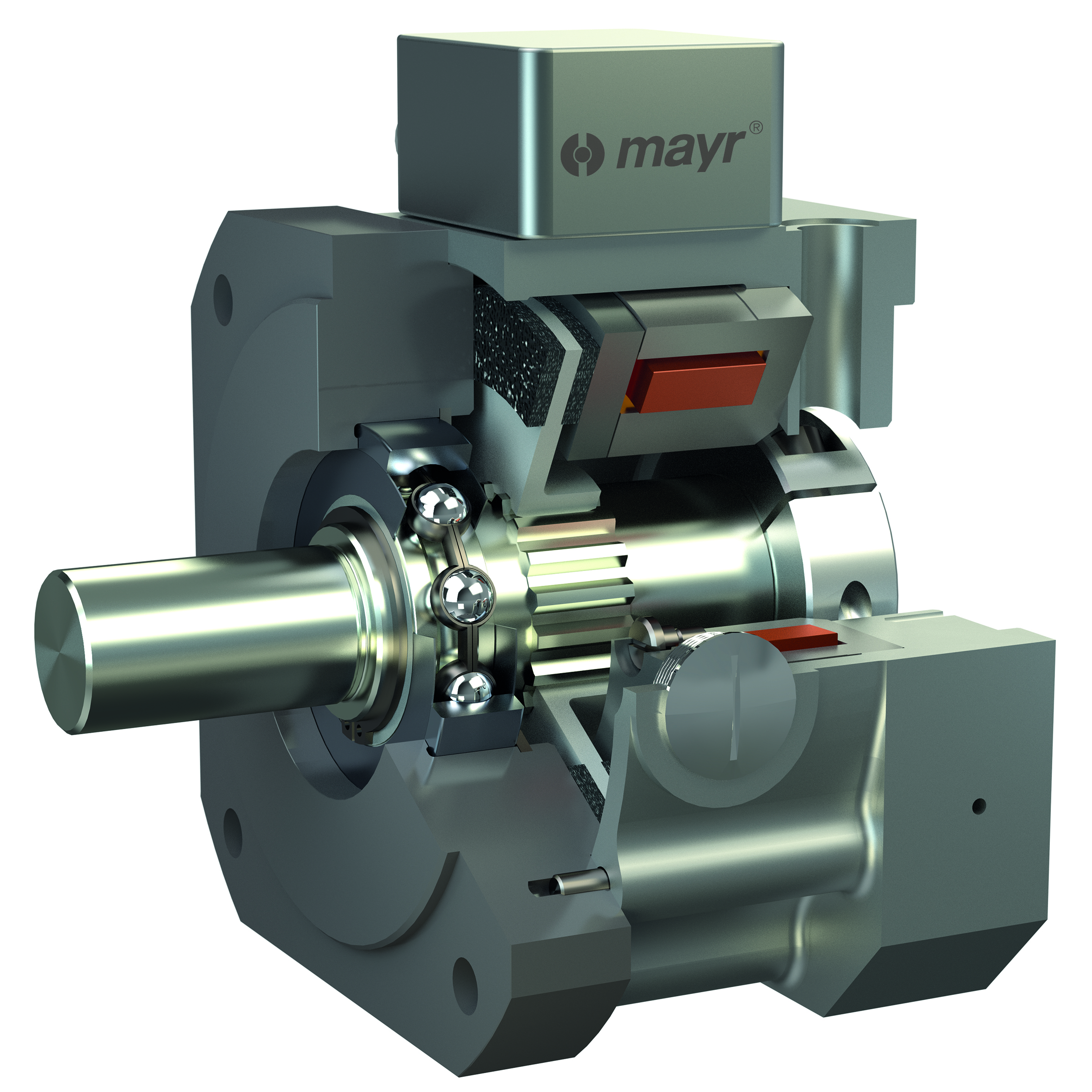
Mechanical, electric, fluidic, and self-actuated clutches and brakes are suitable for different applications. For example, spring-set brakes benefit motion designs that slow loads with the motor before the brake engages … and they’re suitable as holding mechanisms. Control of electric brakes is easy, and they can keep pace to a thousand cycles per minute. Most air-actuated brakes and clutches are cool-running and hold with minimal input. Friction brakes with drum, disc, and cone geometries deliver e-brake functionality with failsafe holding.
Brake or clutch size and type depend on whether the axis at hand will make emergency stops or softer stops that sacrifice the clutch or brake to protect systems and loads from shock. Or sometimes it’s more essential that the brake deliver soft stops to prevent shifting loads and misalignment. After that, other criteria — cycle rates, thermal capacity, machine envelope, and MRO schedules — dictate final selection.
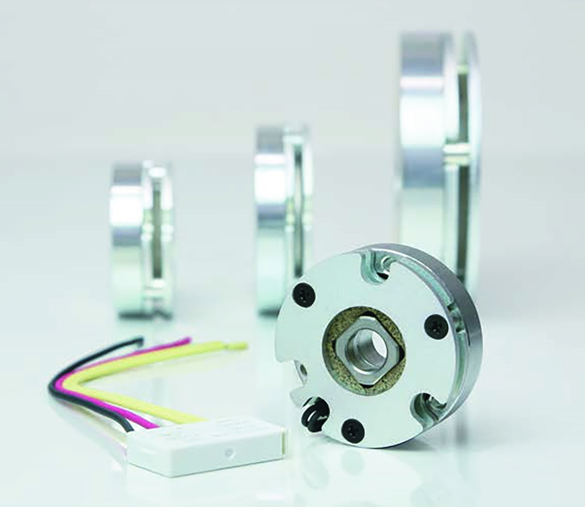
Some tips: Size clutches and brakes to the machine axis’ motor torque. Where a brake must stop vertical loads, account for how motors can briefly draw current to output in excess of their rated torque. Consult performance curves in manufacturer PDFs for dynamic torque ratings at set speeds to match the brake or clutch to peak motor-output torque. Case in point: Consider an inclined conveyor with regularly spaced on-off cycles. Here, a power-off spring-set brake may suffice to prevent load crashes during power failures. But more complex conveyor installations to position discrete product of varied size — without jerking — may need multiple deceleration rates may need more sophisticated spring-set brake plus drive on the motor for stopping … or even a permanent-magnet brake for quick yet soft starts and stops.
Comparing clutch and torque-limiter functions
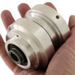
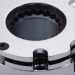
Torque limiters are not clutches, as they’re not designed to continuously slip. That’s an important distinction when design engineers are specifying slowing and disengaging technologies for mechanical designs. Some tips for optimal design selection: First consider whether a torque limiter will only protect against catastrophic failure or semi-regular overloads. That will indicate whether an economical friction-style torque limiter is sufficient or if the design necessitates a ball-detent design. The latter is usually more costly but capable of slipping and triggering a limit switch for shutoff and resetting to resume operation. Ball-detent torque limiters here can slip multiple times in their application … unlike friction torque limiters requiring reset.
When applying a torque limiter, confirm whether a zero-backlash design is needed. Note that torque limiters can generate heat at their frictional connections, so upon their activation, system shutdown is key. After it’s activated, the end user should inspect the torque limiter for wear and heat damage. He or she should also check its setting torque … as in some designs, that value will be diminished if the torque limiter has been run too long. As long as the torque limiter is still within design range, it’s safe from exhibiting more and more slipping. With some motion designs, a limit or proximity switch paired with controls can detect when the torque limiter slips — and shuts the system down to let the end user address the issue the torque limiter was protect (or protect against). || Insight into torque-limiter functions provided by KTR engineering services manager Chris Scholz.


Leave a Reply
You must be logged in to post a comment.