Feedback-equipped stepper motors are not a complete substitute for servomotors, but they can provide a reliable alternative for many real-world applications. These motion-design solutions improve machine performance without breaking the bank.
By Jim Stevens • Product Specialist | POSITAL Inc.
Stepper motors are a top choice for many motion and position control applications. They’re available in a wide range of sizes and torque ratings and are significantly less expensive than high-end servomotors. So, let’s talk about ways of raising stepper-motor performance to that of servomotors by adding feedback devices.
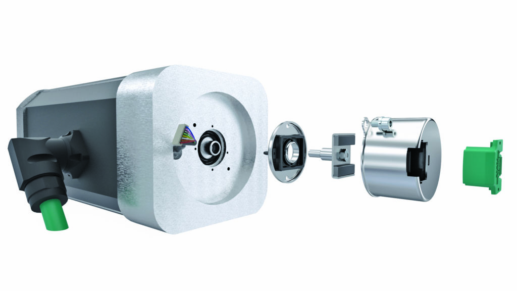
Stepper-motor benefits and drawbacks to address
Stepper motors are brushless dc electric motors that move in discrete steps rather than continuously sweeping rotational motion. These step motions are driven by magnetic field shifts by sets of electromagnetic coils in the stator. Stepper motor operation depends on a controller — an electronic device that feeds current to the motor’s stator coils in a sequence that drives step motions. The controller’s capabilities has significant impact on motor performance.
There are several types of stepper motors available, but the most common varieties offer good resolution (200 steps per revolution or better) as well as respectable low-speed torque, rugged construction, long service life, and relatively low cost. However, they do have limitations. Torque output drops off at higher rotational speeds and (with simple controllers) stepper motors can be subject to ringing — high-frequency vibrations. The biggest drawback is that even in positioning applications, basic stepper-motor systems operate under open-loop control.
Stepper motors respond to instructions from the controller to move a certain number of steps — but return no feedback to the controller about whether this motion has been completed. So if the motor fails to complete requested step motions, a growing discrepancy can arise between what the controller assumes as the motor shaft’s rotary position and the true position of the shaft (and any attached loads or driven mechanisms). Such mismatches happen when the motor’s torque is insufficient to overcome mechanical resistance … and in fact, these mismatches can become a significant problem at high rpm, because that’s when motor torque-output capabilities are limited. That’s why design engineers often overspecify stepper motors — to avoid missed steps, even if it makes for stepper-motor selections that are overly large and heavy for all but the most demanding motion profiles.
Another drawback is that when a traditionally applied stepper motor comes to a stop, current must flow through the motor windings to hold the stepper-motor shaft in position. This consumes electrical power and heats the motor windings and surrounding subcomponents.

Feedback on stepper-motor systems for reliable positioning
Adding encoders to a stepper-motor system to get shaft-position feedback essentially closes the control loop. Adding these feedback devices increases overall system cost, but not as much as switching to a servomotor.
One approach for adding encoder feedback is to operate in move and verify mode. In this case, a simple incremental encoder is added to the stepper motor’s tail shaft. Then when the controller issues step commands to the motor, the encoder continuously verifies to the controller that the commanded motions have occurred. If the motor fails to complete the requested number of steps, the controller can request more steps until the motor reaches the intended position. More sophisticated controllers also increase the phase current into the motor as a way to boost torque for making those extra steps.
Encoders used in such move-and-verify setups typically have resolutions that are some multiple of 200 positions per revolution.
Note that setups employing move-and-verify modes may still benefit from the inclusion of oversized motors, but not oversized to the degree required by simple open-loop systems.
Also note that this mode can help intelligent controllers finetune holding currents into the motor for slight efficiency improvements during stopping … though overall energy consumption still tends to be high.
Closed-loop stepper control with absolute encoders
Another somewhat more sophisticated option for critical position-control applications is full closed-loop control employing multiturn absolute encoders. Encoders used here attach to a stepper motor’s tail shaft to monitor:
• The stepper motor’s angular position as well as
• The stepper motor’s number of full turns.
In this configuration, the stepper motor is controlled like a high-pole-count brushless dc (bldc) motor … and the encoder continually provides position feedback to the controller. Holding current supplied to the motor is then exactly tailored to the amount required to maintain position within a given position tolerance. A stepper motor controlled like a brushless servo motor is energy efficient and less expensive than a true bldc servomotor. So, why not use low-cost stepper motors for all bldc servo applications?
Well, stepper motors used in closed-loop servo systems have a physical limitation not found in true BLDC servomotors. More specifically, stepper motors thusly operated are essentially working as 50-pole brushless motors, so can’t achieve the rpms possible with servomotors. In addition, stepper-motor rotors have higher inertia than those of true bldc servomotors of equivalent power … so can’t deliver the same accelerations.
When a stepper motor is used in bldc mode, the encoder performs a vital commutation role — reporting the motor shaft’s exact rotary position … which in turn lets the controller energize the appropriate set of stator electromagnets for continuous rotation as needed. In addition, precision absolute encoders can also help advanced microstepping controllers in finetuning the phase current to reduce the ringing (vibration) that occurs in more basic stepper-motor systems.
Choosing the right encoder for a stepper-based design
As was mentioned above, simple incremental encoders can be effective when a stepper motor is used in move and verify mode. Incremental encoders also support speed control … although stepper motors aren’t usually the best choice for continuous operation at steady speeds.
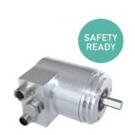
Absolute encoders, which report the shaft’s rotary position, excel on critical positioning axes. These come in self-contained versions (having their own closed housing and shaft) or kit forms. Here’s the difference:
• Self-contained encoders require some form of coupler to connect them to the motor’s shaft.
• In contrast, kit or modular encoders are integrated by the machine builder into a motor or drive mechanism to measure rotary motion directly from the drive shaft. These kit encoders might be built into the motor’s housing or attached externally to the motor’s end bell.
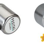
Absolute magnetic encoders, which measure rotations through a set of Hall-effect sensors, are a top option for feedback control of stepper motors. Available in self-contained as well as kit form, they are rugged and relatively insensitive to dust, moisture, and other contaminates … plus are easy to install. Magnetic encoders that take kit form consist of an electronics package (mounted on a small PCB) along with a small permanent-magnet array attached to the rotating shaft. Miniature versions of these encoders in self-contained form (having external diameters down to 22 mm) are available for especially small motors.

Multiturn magnetic encoders can keep track of the motor’s completed number of rotations. Such encoders are useful for control of motors driving loads via reduction gears, worm gears, and cable drums. The rotation counter for these devices is built around a Wiegand sensor that detects complete rotations and provides power for the counter circuitry. This ensures that the rotation count is always accurate, even when rotations occur while system power is unavailable.
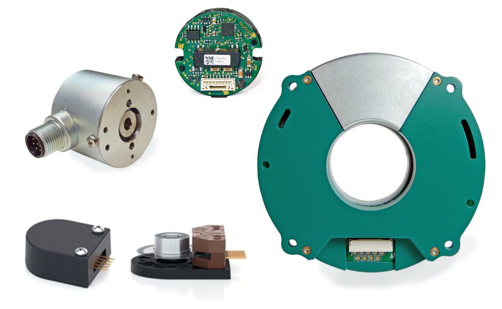
Hollow-shaft kit encoders employing capacitive measurement can be a useful option in cases where it is preferable to install the rotation measurement device on the drive end of larger motors. These are available with multiturn measurement ranges and center openings of 30 and 50 mm.
Posital Inc. | www.posital.com


Leave a Reply
You must be logged in to post a comment.