Inertia is an object’s resistance to a change in speed. To determine the inertia of an object, its mass is multiplied by the square of its distance from the axis of rotation. A familiar demonstration of inertia is a figure skater on the ice. When she spins with her arms close to her body, her mass is close to her axis of rotation and her rate of spin is fast. But when she extends her arms, the distance of her mass from the axis of rotation is increased, making her inertia larger and causing her to spin at a slower rate.
In an electromechanical system, both the motor and load have inertia, and how similar (or different) their inertias are will affect the performance of the system. The ratio of the load inertia to the motor inertia is one of the most important aspects of servo motor sizing.
JL = inertia of load reflected to motor
JM = inertia of motor
Motor inertia is given by the manufacturer, while the load inertia is calculated by adding the inertia of all rotating parts, which typically includes the actuator or drive (belt, ball screw, rack and pinion), the external load, and the coupling.
JL = inertia of load reflected to motor
JD = inertia of actuator or drive (ball screw, belt, rack & pinion)
JE = inertia of external (moved) load
JC = inertia of coupling
For the motor to effectively and efficiently control the load during acceleration and deceleration, the motor and load inertias should, theoretically, be equal. But a 1:1 inertia match is rarely practical or achievable. Many factors influence what inertia ratio is acceptable for a given application, but one of the most import is the compliance, or wind-up, in the system. Mechanical components are not perfectly rigid, and the more components—belts, couplings, and gearboxes—in the drive train, the more compliance the system will have. In general, the higher the compliance, the lower the inertia ratio should be in order for the motor to effectively control the load.
While there’s no formula for determining the best inertia ratio, some motor sizing guidelines stipulate that the the inertia ratio should be 10:1 or lower. Higher mismatches cause the motor to draw more current than necessary, which decreases efficiency and increases operating costs. A higher ratio also increases resonance and can cause the system to overshoot the desired velocity and position, negatively affecting performance.
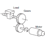
If the inertia ratio is too high, there are two ways to reduce it: add a gearbox to the system, or use a larger motor. Gearboxes are frequently used in belt driven systems to optimize the motor speed and torque. But they can also significantly reduce the inertia ratio of the system, since the gear ratio has an inverse square effect on the inertia of the load.
JG = inertia of gearbox
i = gear ratio
The second method for reducing the inertia ratio is to use a larger motor with higher inertia. However, this is rarely a beneficial solution in the long term, since a larger motor costs more, requires more torque to overcome its own inertia, and consumes more energy, which increases the system’s total cost of ownership.
On the other hand, an inertia ratio that is unnecessarily low, or even a “perfect” 1:1 match, can indicate that the motor is oversized, which results in unnecessary cost and energy consumption. Rather than striving for a perfect inertia ratio, designers should take into account the system dynamics and positioning requirements and strive for an inertia match that achieves these requirements with a servo motor that is neither over- or under-sized.


Leave a Reply
You must be logged in to post a comment.