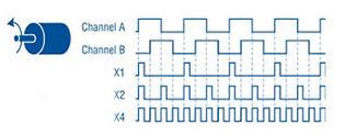
Incremental encoders determine rotary position by generating a specific number of pulses per revolution (PPR) and counting those pulses as the encoder spins. The PPR rating indicates resolution, and is typically the most important factor when selecting an incremental encoder. But how do you determine what PPR is needed for a specific application? Fortunately, establishing the required PPR is not difficult—just follow a few guidelines.

Distance
When linear motion is being measured, the required pulses per revolution is calculated by dividing the lead of the screw by the linear resolution needed for the application. Conversely, for an encoder with a given PPR, the resulting linear resolution is calculated by dividing the screw lead by the PPR. Keep in mind that if X2 or X4 encoding is being used, this should be factored into the PPR number. For example, if the desired linear resolution requires a PPR of 5000, and X4 encoding is being used, the encoder chosen should have a PPR of 1250 (5000/4).
If the travel is being measured by use of a wheel or roller, a calibration constant might be necessary, depending on the required display resolution. The calibration constant is calculated by dividing the wheel or roller circumference by the PPR of the encoder, multiplied by the gear ratio being used (if any). This is then multiplied by any conversion required to translate from the wheel/roller circumference units to the desired units for the display. (For example, multiply by 1000 to convert from circumference in meters to display units in millimeters.)
K = calibration constant
C = wheel or roller circumference (typically inches or meters)
G = gear ratio
N = encoder PPR
Using a calibration constant or scaling factor has the drawback of introducing a rounding error that will accumulate over many cycles of the encoder. To avoid this, choose an encoder whose PPR is an even multiple of the value that is being measured. For example, if one revolution of the encoder equals 12 inches, choose a 1200 PPR encoder.
Speed
Another important factor in determining the required pulses per revolution is the encoder’s maximum speed—both mechanical and electrical. The mechanical speed limit is based on the maximum speed that can be obtained without causing potential damage to the encoder. The electrical speed limit is determined by the maximum frequency response of the encoder’s electronics—that is, how fast the electronics can switch between “On” and “Off.” The lower of the two values—mechanical speed or electrical speed—indicates the maximum speed the encoder can turn. To convert electrical speed to rpm, the frequency response is divided by the PPR and multiplied by 60 (seconds per minute). Again, if X2 or X4 encoding is being used, the PPR must be multiplied by 2 or 4, respectively.
For example, consider an encoder that is rated at 100 PPR with a maximum mechanical speed of 3000 rpm and a maximum frequency response of 100 kHz. The electrical speed is 60,000 rpm, so the mechanical speed, at 3000 rpm, is the limiting factor.
An encoder is just one part of a complete electromechanical system, so it’s important to also ensure that the maximum encoder speed doesn’t exceed the maximum input frequency of the device the encoder is driving.


Leave a Reply
You must be logged in to post a comment.