 Updated May 2019. || Dc motors are motion components that take electrical power in the form of direct current (or some manipulated form of direct current) and convert it into mechanical rotation. The motors do this through the use of magnetic fields that arise from the electric currents to spur rotation of a rotor fixed with an output shaft. Output torque and speed depends on the electrical input and motor design.
A direct current (dc) motor is an electric machine that converts electrical energy to mechanical energy.
According to the most common industry naming conventions of today, there are three dc motor subtypes: Dc brush motors, dc permanent-magnet (PM) motors, and dc universal motors. As we’ll see, there are some caveats and sub-classifications.
Many larger dc motors still employ brushes and wound fields … though PM motors dominate fractional and integral-horsepower applications below 18 hp, and PM motors are increasingly common for myriad designs.
What kinds of dc motors are there?

Some engineers call dc brush motors wound-field motors, because it’s a wound and lacquered coil of copper wire that makes the electromagnetic field. Some engineers also argue that all dc motors are brush dc motors, and that the term “brushless dc motor” is a misnomer.
No matter the term, there are permanent magnet, shunt, series, and compound-wound brush dc motors.
All except the former use two currents:
1. Current through armature (rotor) windings to interact with a stator magnetic field (for output of mechanical rotation) and
2. Current through stator windings to make the magnetic field in question.
In contrast, permanent-magnet brush dc motors use:
1. Current through armature (rotor) windings to interact with a stator magnetic field (for output of mechanical rotation) and
2. Permanent magnets on the stator to make the magnetic field in question.
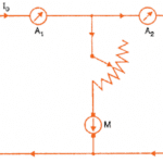
The armature and field coils in a shunt-wound motor connect in parallel so the field current is proportional to the load on the motor.
The armature and field coils in series-wound motor connect in series so current passes only through the field coils.
The armature and field coils in compound-wound motors include both series and shunt windings.
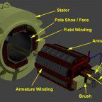
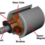
No matter the setup, brush dc motors have commutators and brush contacts to pass current to the rotating rotor’s copper-wire windings. Designers can control speed by changing rotor voltage (and current with it) or by changing the magnetic flux between rotor and stator through adjustments of the field-winding current. Brush orientation to the rotor’s commutator bar segments mechanically controls the phase commutation.
Read the related article: What are coreless dc motors?
 In fact, the way dc brush motors let designers control field and rotor windings means they’re suitable for applications that need simple and cost-effective torque and speed control.
That said, increased functionality from electronics for PM motors means that this advantage in less pronounced than it once was. What’s worse, current on both rotor and stator generate heat that limits the motors’ continuous-current ratings. The motors also present a spark hazard, so can’t go in explosive settings. At certain periods during the dc motor rotation, the commutator must reverse the current, reducing motor life with arcing and friction. So, brushed dc motors require more maintenance in the form of replacement of springs and brushes that carry the electrical current, and replacement or cleaning of the commutator. These components are important for transferring electrical power from outside the motor to the spinning coil windings of the rotor inside the motor.
Note: The brushes in dc brush motors wear and need replacing, and brush-wear particles mean that designers shouldn’t use dc brush motors in cleanrooms. Same goes for applications that need high precision, as friction from brush-commutator engagement make for long position-settling times.
Series-wound dc motors
As mentioned, the armature (rotor) and field coils in series-wound motors connect in series. That means the entire armature (rotor) current passes to the field winding. So, these motors only need one input voltage supply. Torque equals current squared. Increasing armature (rotor) current induces a field-current increase. Regenerative braking isn’t possible; field current collapses when rotor current passes through zero and reverses.
Torque is highest when the motor stops because the armature (rotor) generates no back electromotive force (bEMF) when at rest. When the armature (rotor) accelerates, bEMF increases. That in turn reduces effective current, voltage and torque. Without loading, the motor accelerates to dangerous speeds. In contrast, increased load slows the motor but lowers bEMF … and increases torque to turn the load.
Series-wound motors can’t regulate speed well, as speed control depends on adjustments to the supply voltage. Even so, they’re inexpensive and can drive designs that need high starting torque. For example, designers use series-wound motors in low and high-power automotive mechanisms, consumer products such as power tools, toys, and sewing machines, and industrial traction drives with fixed and variable speed. Designers can reverse series-wound motors by reversing field or armature (rotor) winding connections.
Shunt-wound dc motors
As mentioned, armature and field coils in shunt-wounds motor connect in parallel … so field current is proportional to the load on the motor. Variable-voltage input allows for speed adjustment. Supply fixed voltage to a shunt-wound motor to make it run at constant speed. Then supply increasing motor current to a shunt-wound motor to increase torque without significant slowing.
In shunt-wound motors, the field (stator) winding connects in parallel with the armature (rotor) winding.
With these motors, a technique called field weakening can control speed without forcing the controls to change input voltage. A field-winding rheostat reduces field (stator) current and with it the magnetic flux between armature and field — across the airgap that separates them. Speed is inversely proportional to flux, so this accelerates the motor. One caveat: Torque is directly proportional to flux, so the acceleration comes with diminished torque output.
Stabilizing windings prevent acceleration as load increases at weak field settings. The only catch is that reversing applications need reversal of this winding to go with armature (rotor) voltage reversal. That necessitates reversing contactors. So for reversing motion, sometimes manufactures just design shunt-would motors with higher stability and omit stabilizing windings.
Note: The operation of a permanent-magnet brush dc motor is much like that of a shunt-wound motor, save for the mode of field-flux production.
Reversing a shunt-wound motor’s connections on either rotor windings or field reverses the motor’s direction of rotation; self-excitation maintains the field when the rotor current reverses, which means the motors can regeneratively brake.
Shunt-wound motors drive machine tools and automotive fan and wiper applications.
Compound-wound motors
Separately excited motors (sometimes called compound-wound motors) are DC brush motors with independent voltage supplies to the field (stator) and armature (rotor) … for better control over motor output. Input voltage on either winding can control motor output speed and torque. Most manufacturers build compound-wound motors with series and shunt-wound field (rotor) windings. The direction and strength and direction of two windings dictates the motor’s speed-torque curves.
Compound-wound motors work well for traction in automotive or rail-train applications.
Read the related article: What are permanent-magnet dc motors, and what kinds are there?
In summary, dc motors generate a magnetic field via electromagnetic windings or permanent magnets.

In a brushed dc motor, the magnet acts as the stator. The armature is integrated onto the rotor and a commutator switches the current flow. The commutator’s function is to transfer current from a fixed point to the rotating shaft. Brushed dc motors generate torque straight from the dc power supplied to the motor by using internal commutation, fixed permanent magnets, and rotating electromagnets.
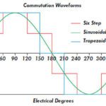
Brushless dc (BLDC) motors, on the other hand, do away with mechanical commutation in favor of electronic commutation, which eliminates the mechanical wear and tear involved with brushed dc motors. In BLDC motors, the permanent magnet is housed in the rotor and the coils are placed in the stator. The coil windings produce a rotating magnetic field because they’re separated from each other electrically, which enables them to be turned on and off. The BLDC’s commutator does not bring the current to the rotor. Instead, the rotor’s permanent magnet field trails the rotating stator field, producing the rotor field.


Leave a Reply
You must be logged in to post a comment.