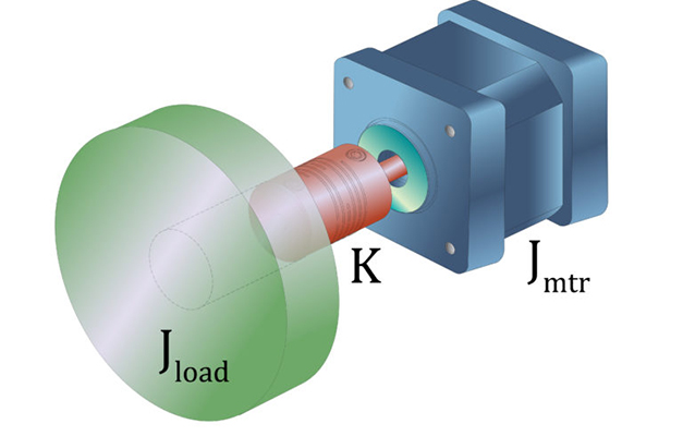
One of the most important parameters when sizing a motion system is the inertia of the load being moved. Regardless of the type of motor being used — AC induction, stepper, brushless DC, or AC servo — the ratio of the load inertia to the motor inertia has an important influence on system performance.

If the load inertia is significantly higher than the motor inertia, the motor will have difficulty controlling the load. Conversely, if the motor inertia is much higher than the load inertia, then the motor is likely oversized, increasing the overall footprint, upfront cost, and cost of operation, and possibly requiring larger components in other parts of the system.
This is why it’s important to understand not only how to calculate the inertia ratio of a motor-driven system, but also how to manage the inertia mismatch to get the best system performance.
Inertia is determined by the mass being moved and the distance between the mass and the axis of rotation. For a point mass, the equation for inertia is simply:
![]()
JL = load inertia (kgm2)
m = mass of load (kg)
r = distance from center of load to axis of rotation (m)
The first way to manage the load-motor inertia ratio is to keep the load inertia as small as possible, taking into account that each part of the system that is directly or indirectly attached to the motor — including couplings, linear guides, drive components, and the applied load — contributes to the load inertia. And although the load itself is often fixed in size, shape, and mass, it may be possible to change other components in the drivetrain to reduce the load inertia.
For example, if the load is driven by a ball screw that is significantly oversized (larger diameter or longer length than necessary), changing to a smaller screw that better fits the application will reduce the load inertia and improve the inertia ratio.
There is also the issue of compliance, or lack of stiffness, in the system, which is made worse with each connection point in the drivetrain. This lack of stiffness exacerbates the inertia mismatch (high load-to-motor inertia ratio), leading to increased response times, lower system bandwidth, and resonance.
Some changes in the drivetrain can both improve the inertia mismatch (reduce the inertia ratio) and reduce compliance. For example, switching from a traditional ball screw to a driven nut assembly can substantially reduce the inertia of the drive, because in a driven nut system, only the nut is rotating, rather than the entire screw shaft.
Similarly, rack and pinion drives often have lower inertia for a given travel length than traditional screw or belt drives, since only the pinion moves (assuming the rack is stationary and the pinion is driven). And both screw and rack and pinion drives have less compliance and better stiffness than belt drives, making them better suited to handle a higher inertia mismatch.
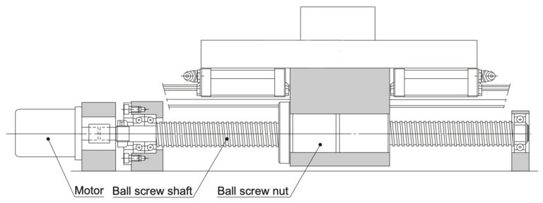
Image credit: THK
However, keep in mind that in both rotating nut and rack and pinion systems, the motor moves along with the nut or pinion, so its mass now contributes to the load inertia. In applications where the applied load is small, this can make the system inefficient, since it leads to a situation where the motor uses a considerable amount of its torque to move its own mass. But if the applied load is large, the additional mass of the motor won’t significantly increase the required torque.
Check out Linear Motion Tips for tutorials on how to calculate inertia for various types of systems:
- Inertia of a ball screw driven system
- Inertia of a belt driven system
- Inertia of a rack and pinion driven system
When a direct drive motor — such as a linear motor or rotary torque motor — is used, inertia becomes less influential on system performance, since couplings and gearboxes, which add compliance, have been eliminated. The main factors determining system performance for direct drive applications are the stiffness of the mechanical system and the bandwidth of the control system.
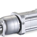
Another method to manage load inertia is to add a gearbox to the system. This reduces the amount of load inertia reflected to, or “seen,” by the motor. And the load inertia is reduced by the square of the gear ratio, so a relatively small (low ratio) gearbox can make a material difference in the load inertia seen by the motor. But keep in mind that if the other benefits of adding a gearbox — increased torque to the load and increased motor speed — aren’t necessary, this can be a costly way to address high load inertia. A gearbox also adds compliance to the system, requires additional space, and reduces efficiency.
Fortunately, the “old” rules of inertia matching — which encouraged designers to strive for an inertia ratio of 10:1 or lower — are out. In most modern-day applications, good system performance can be achieved even with very high inertia ratios, thanks to sophisticated servo drives with capabilities such as cascaded control loops and adaptive tuning, as well as more accurate system modeling and simulation tools. One such tool is the Bode plot, which plots the system’s amplitude and phase response at different frequencies. To learn more about Bode plots, check out this article on frequency response and this article on inertia matching.




Leave a Reply
You must be logged in to post a comment.